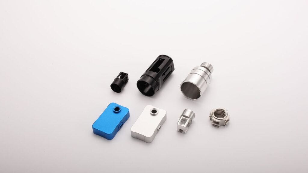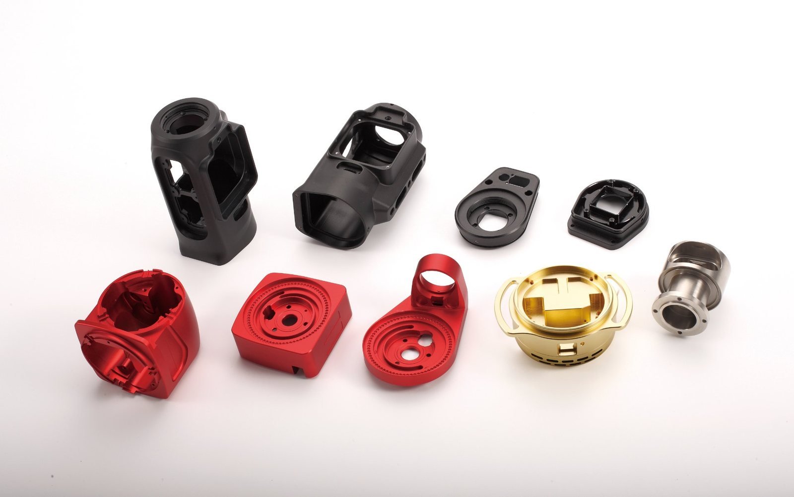
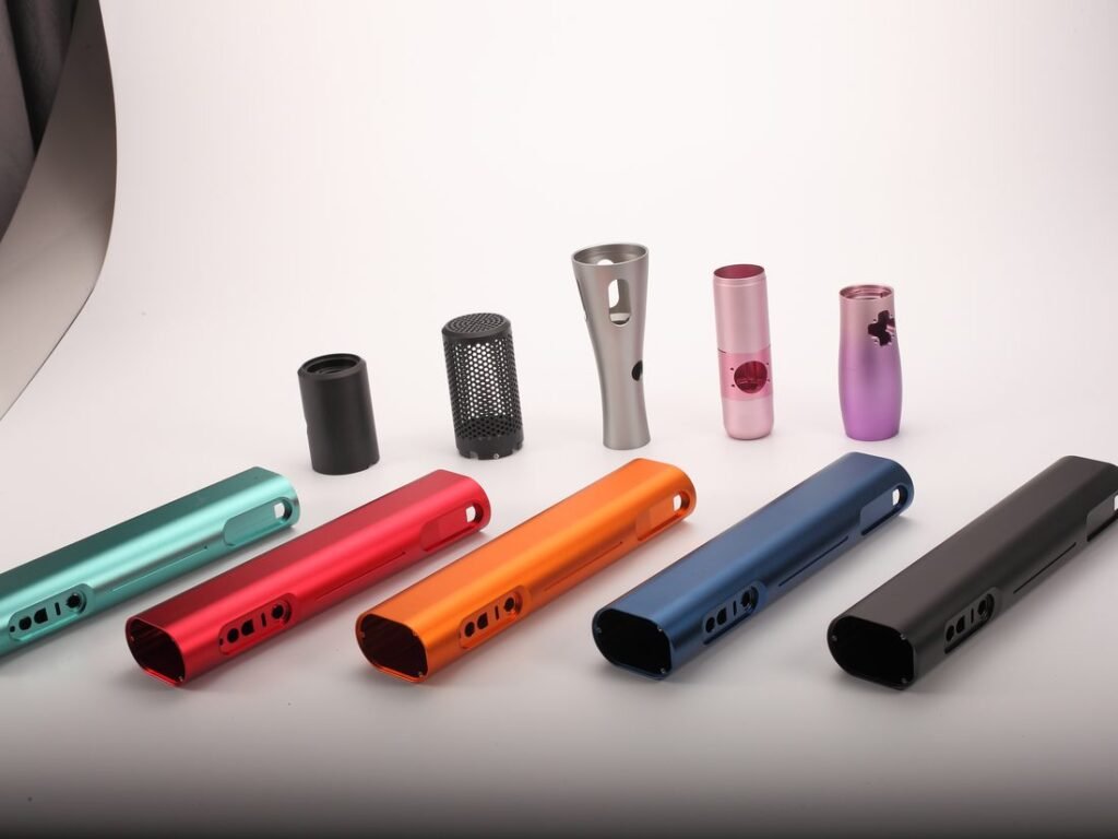
Anodising is the most common finish on machined aluminium, and the most common source of arguments after delivery. The reason is simple: anodising is not a coating that covers a surface, it is a conversion layer grown out of the metal itself. That changes how it behaves on dimensions, on alloy choice, and on colour.
What anodising actually does
The part goes into an acid electrolyte and becomes the anode. Oxygen released at the surface converts aluminium into aluminium oxide, growing outward and inward at the same time. The result is a hard, electrically insulating ceramic-like layer that is part of the part — which is why it cannot flake off like paint, and why it also cannot hide what is underneath. Tool marks, scratches and polish lines stay visible through an anodised finish.
Type II versus Type III
- Type II (sulphuric anodising) is the everyday decorative finish. Typically around 0.0002–0.0005 in (5–12 µm) per side, available in clear or almost any dyed colour, and it handles most consumer electronics, robotics and industrial housings.
- Type III (hard anodising) is thicker and denser, typically 0.001–0.002 in and above, with better wear resistance and lower dyeability — dark colours are easier than bright ones. It suits sliding surfaces, wear pads and parts that get handled aggressively.
Both are usually quoted against a cosmetic requirement rather than a thickness number alone, because colour and appearance are what buyers actually judge.
Where anodising changes your dimensions
The layer grows both ways, so roughly half the total thickness is added to the outside of the surface. On loose tolerances this is irrelevant. On precision fits it is not: a shaft got 0.02 mm smaller on one side, a bore got 0.02 mm smaller in diameter, and a thread that was a comfortable fit before finishing can be tight afterwards.
The practical answers, in the order we usually recommend them:
- Mask threads, press fits and bearing bores on the drawing, and say so explicitly.
- Allow for the build-up on any dimension that changes — or machine those surfaces after finishing.
- Keep hard anodising away from sharp edges, which tend to chip; specify an edge break instead.
Alloy choice decides how it looks
- 6061 anodises predictably and takes dye evenly — the default for cosmetic housings.
- 7075 is stronger but tends to come out darker and slightly less uniform, especially in clear anodising.
- 2024 and high-copper alloys are poor candidates for decorative anodising; the copper phases discolour and blotch the surface.
If appearance matters, decide the alloy before the parts are made. It is not something finishing can correct afterwards.
Colour drift is normal — consistency is a process decision
Anodising is a wet chemical process. Dye concentration, temperature, dwell time and the alloy batch all move the result, which is why two batches done a month apart can differ by an amount that the eye catches immediately when the parts are side by side. If your product has parts from different batches visible in the same assembly:
- Tell us up front — we can hold a batch or plan a single finishing run for matching parts.
- Accept a colour range rather than an exact match, or approve a physical sample that we keep on file.
- Specify machining in one batch where the surface finish needs to match, rather than splitting the order.
How to specify it on the drawing
- Process: Type II or Type III, clear or dyed (with a colour reference).
- Which surfaces: all over, or listed cosmetic faces only.
- Masking: threads, bores, electrical contact areas, laser-marked areas.
- Appearance: sample photo or reference part, and whether light machining marks are acceptable.
- Anything that must not change dimension after finishing.
For most machined aluminium parts, the honest specification is “Type II, clear or black, cosmetic on the visible faces, mask the threads, no sharp edges” — plus a photo of what good looks like. That is enough for us to quote, make and inspect without a round of emails.
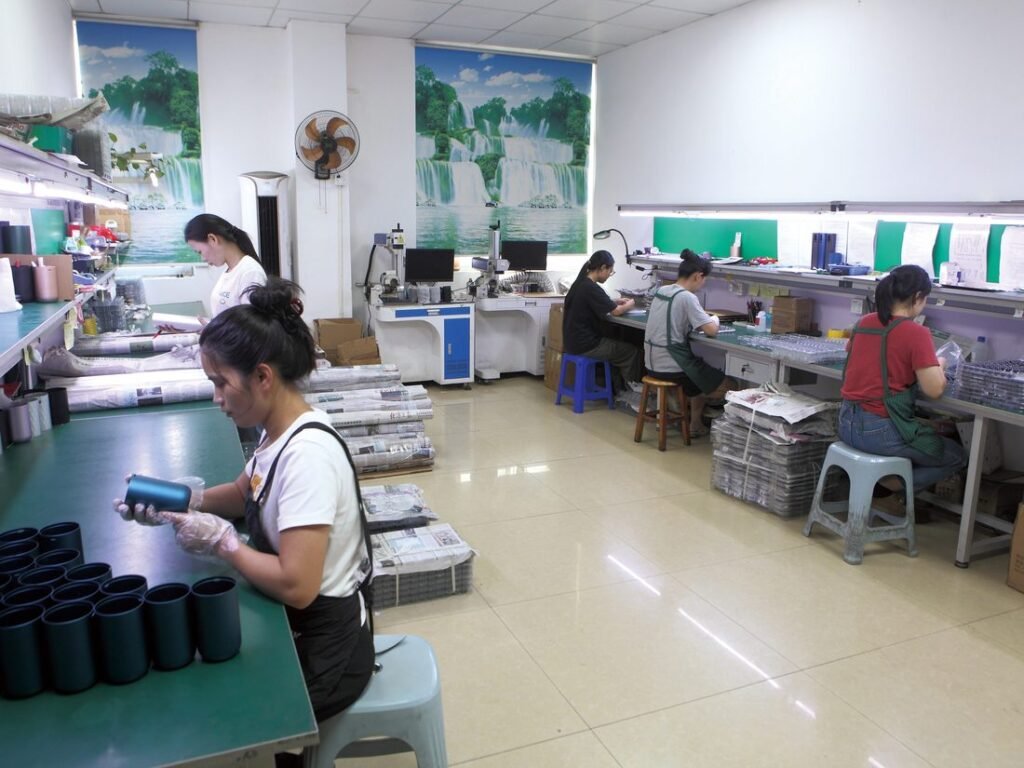
Finishing is run through a partner network that we manage and inspect on your behalf, so the anodising is specified, checked and shipped as part of the same order. See surface finishing for the processes we quote most, or send a drawing to info@xinwinfhardware.com.
We quote, program, machine and inspect custom parts in Shenzhen — turning, milling, Swiss-type and finishing. Everything in this blog comes from drawings we have actually run, including the mistakes. Questions about your part? Email info@xinwinfhardware.com.